
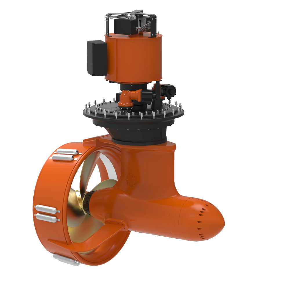

Thrustmaster tunnel thrusters are easy to install. The whole unit has already been installed in a section of tunnel and all you need to do is install this section of tunnel in the hull.
With hydraulic tunnel thrusters, orientation is not critical. You can direct the strut opening straight upward, down, fore, aft, or at any angle that optimizes the hydraulic piping layout. With engine or electric drive thrusters, the lube oil vent port to the head tank should be as high as practical.
The tunnel length can be extended by butt-welding pipe of the same material, diameter, and wall thickness to the ends of the standard three-foot tunnel section of the thruster. As an alternative, order your thruster with extended tunnel length (specify total tunnel length with your order) to save time and money during installation.
When adding a tunnel thruster to an existing vessel, cut tunnel openings in the hull plating and longitudinal bulkhead (if any) and slide the thruster into the hull from one side until it is in the desired position. Weld the tunnel ends to the hull plating or fairing pieces and weld the tunnel to longitudinal structural members so that the tunnel becomes an integral part of the vessel structure.
Proper submergence of the tunnel entrance is necessary to prevent vortexing and air entrainment. When air is entrained in the tunnel flow during operation, the thruster will cavitate, resulting in excessive noise, vibration, substantial reduction of thrust output and possible damage to the thruster. As a minimum, the top of the tunnel must be one tunnel diameter (1D) below the minimum light draft waterline of the vessel.
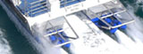
If two or more tunnel thrusters are installed in tandem, the center of each tunnel should be two times the tunnel diameter (2D) apart (see Fig. 1 below).
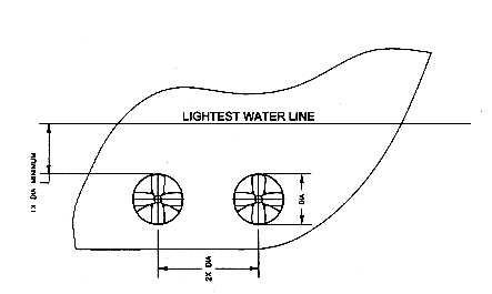
Figure 1: Typical tunnel thruster location
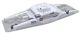
Tunnel thrusters for bow and stern maneuvering applications should be installed as far forward or aft in the vessel as possible. This increases the effective turning moment lever arm around the vessel’s natural center of rotation. It is generally recommended that the propeller be placed near the ship’s centerline so that equal thrust is available to port and starboard (see Fig. 2 below).
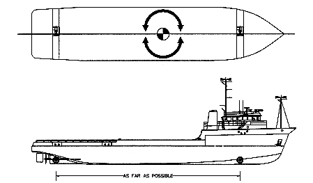
Figure 2: Typical tunnel thruster placement
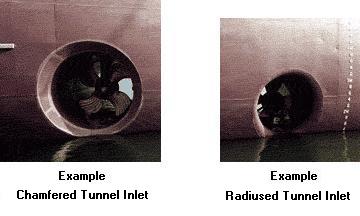
For maximum thrust production, fairing of the tunnel entrances with the hull shell plating is strongly recommended. Fairing the tunnel with the shell plating will substantially improve the thruster’s efficiency. The recommended tunnel entrance fairing is chamfered. Chamfer fairing should be 45 degrees and ten percent of the tunnel diameter (0.1D). (see Fig. 3 below).

Figure 3: Typical tunnel fairing chamfer
In addition to fairing the tunnel entrances for thruster performance improvement, the tunnel entrances may be faired back conically to reduce drag or hull resistance (see Fig. 4 below).
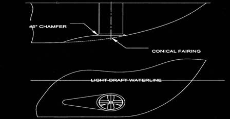
Figure 4: Typical conical hull fairing
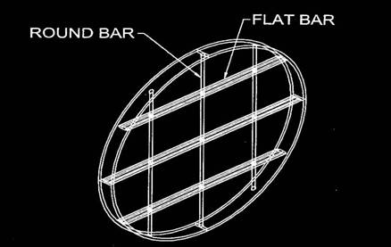
Inlet grids are generally not required on hydraulic tunnel thrusters. The torque limiting hydraulic drive design and low rotation of inertia of hydraulic tunnel thrusters allow them to be stalled without damage. The absence of inlet grids allows easy access to the propeller for inspection and removal of debris. However, if frequent operation in waters with substantial floating debris is anticipated, inlet grids are recommended. Grids are also recommended if the thruster may be used in waters where swimmers or divers are present. Depending on tunnel size, use two to four grid bars evenly spaced at both tunnel entries. Grid bars should be made of flat bar with round edges and spaced with round bar (see Fig. 5 below).
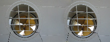
The flat bar should be aligned parallel to the predominant water flow direction generated by vessel bow wave for least resistance, typically about 15 degrees (see Fig. 6 below).
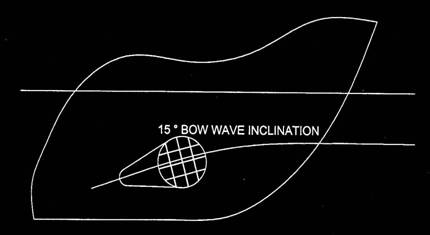
Figure 6: Typical tunnel grid installation
The tunnel section provided with the thruster may be extended by butt-welding to pipe of compatible material. After welding in place, the tunnel inside wall must be sand blasted and painted with a suitable marine coating system to prevent corrosion. Please note that the inside of the tunnel has been provided with a special ceramic coating to prevent erosion by entrained particulates such as sand and silt. Pay special attention to sand blasting to prevent removal of this coating. Do not aim the sand-blasting stream towards the propeller shaft seal of the thruster.
If sacrificial anodes are used, they should be Mil-Spec MIL-A-18001 for zinc anodes, Canada Metals or equal. These type anodes contain additional cadmium (~0.1%), which causes the anode to erode from the surface inward, giving a sand blasted appearance to the surface as the anode is consumed. When the anode is ten percent or less than its original size, it should be replaced. If anodes are installed, they must be placed in the tunnel lengthwise. Anode cross section should not exceed 1 by 2 inches (25 by 50 millimeters).
