

Thrustmaster hydraulic tunnel thrusters can be powered by open loop or closed loop hydraulic systems. The simplest and least expensive system is an open loop system using a fixed-displacement pump and a directional control (“bang-bang”) valve. The valve is solenoid operated and controlled with an electrical signal from the joystick in the pilot house (See Figure 1 Below).
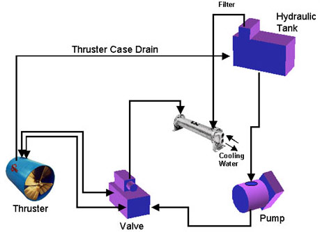
Figure 1: Simple open loop hydraulic system
This system is adequate for smaller thrusters used for docking. It is basically an “on-off’ system giving full thrust when moving the joystick in port or starboard direction. The hydraulic schematic for this system is shown in Figure 2 below.
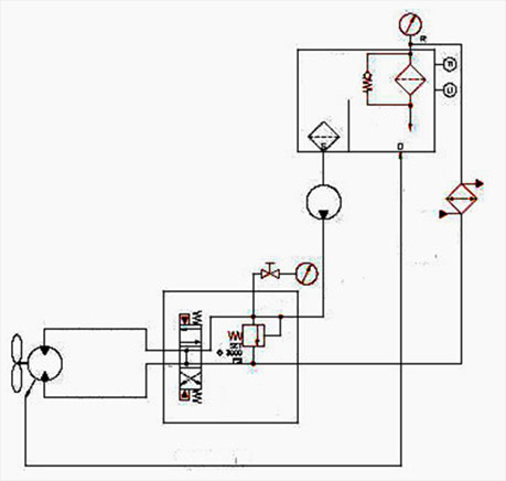
Figure 2: Hydraulic schematic of simple open loop system
Many applications demand proportional thrust control. This means that the thrust increases proportionally to the amount that you move the joystick in port or starboard direction. This can be accomplished with an open loop system by using a proportional directional control valve. It can also be done using a closed loop hydrostatic system.
In an open loop system, the proportional valve meters the amount of flow directed to the thruster. The flow rate is directly proportional to the propeller speed. When using a fixed displacement hydraulic pump, the excess flow produced by the pump is dumped across the relief valve. Having this happen is not good. For example, if you operate the thruster at half speed for a while, the propeller absorbs not more than 20% of rated power, yet the hydraulic pump is producing full flow at relief valve pressure. This means that more than 80% of the power is going to waste, producing a lot of heat and noise. The hydraulic system will soon overheat unless the cooler is sufficiently oversized to dissipate all the wasted energy.
The proper way is to use the more expensive pressure-compensated variable displacement pump. This type of pump will produce no more flow than what the proportional value meters to the thruster.
So if the propeller runs at half speed consuming 20% of rated power, the pump produces only half of its flow at compensator pressure, absorbing half of the rated power. This means that a good 30% of the power is still going to waste, but it is a lot better than 80% when using the fixed displacement pump.
Partial load efficiency of the system can be further improved by using load sensing with a pressure and flow compensated pump. Not only will the pump adjust the flow to whatever the valve demands, the pump will also adjust the pressure to whatever the propeller requires at that time. The load sensing function requires a differential pressure of a few hundred PSI, so there is still wasted energy at the valve, but it is only in the range of 5 to 10%. A typical hydraulic schematic of an open loop system with proportional thruster controls is shown below in Figure 3.
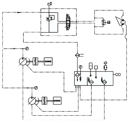
Figure 3: Hydraulic schematic of open loop system with proportional control
The most efficient hydraulic system is a closed loop hydrostatic transmission. This is the most expensive system and yet the most commonly used system to drive Thrustmaster tunnel thrusters. This system does not use a directional control valve at all. The electrical signal from the joystick goes straight to the pump and proportionally controls pump flow and direction. The main pump ports connect directly to the main thruster ports and hydraulic fluid can flow in either direction, providing smooth and fast responding proportional control of thrust between full port and full starboard.
A loop flushing valve or hot oil shuttle valve takes out some of the fluid into the closed loop for filtering and cooling. This is replenished by the charge pump which keeps the closed loop charged to a few hundred PSI, preventing cavitation at the pump and thruster motor. The charge pump is usually integrated in the main hydrostatic transmission pump. A typical hydraulic schematic of a closed loop system is shown below in Figure 4.
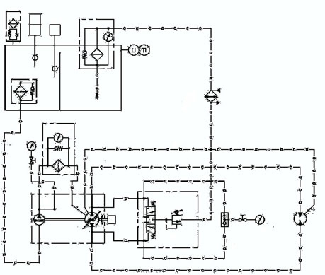
Figure 4: Hydraulic schematic of closed loop hydrostatic system
Thrustmaster can supply the hydraulic system and controls with your tunnel thruster. You can also put your own hydraulic system together based on the guidelines provided here. You may also use an existing hydraulic system such as a central hydraulic system that also powers winches, stabilizers, deck cranes, or other hydraulic equipment.
Hydraulics are very reliable, provided that the system is properly designed and the hydraulic fluid is kept very clean and within normal temperature limits. Use ISO-46 premium grade anti-wear hydraulic fluid. Many hydraulic systems fail at or shortly after start-up. This is usually due to improper or insufficient cleaning of the system, especially the piping and the hydraulic fluid. Carefully follow the recommendations for cleaning and filtering of the system per the Thrustmaster manual that comes with your thruster. The hydraulic fluid lubricates all moving components in the pump, valves, and thruster. Cleaner fluid translates into less wear and longer equipment life.
Once the system is clean and running, it needs to stay clean. In an open loop system, a full flow return filter must be installed. In a closed loop, a change filter between change pump and main pump, and a return filter must be used. Change flow and return flow should be about 20 to 25 percent of rated thruster flow in a closed loop. Select filters of 10 micron absolute (beta rating 75 or better) or 5 micron nominal (beta rating 2 or better). Generously oversize the filters. Consider that the system may require cold start-ups frequently. Size the filters for low oil viscosity prevailing at start-up. Filter bypass valves should remain closed during normal cold start-up conditions.
The system needs to remain closed to prevent ingress of dirt and moisture. Use a pressurized breather on the reservoir, allowing the air buffer in the tank to be pressurized when the system warms up. This eliminates or reduces outside moisture-laden air entering the tanks during cool down of the system.
Temperature of the hydraulic fluid should not exceed 180ºF (82ºC) anywhere in the system. At higher temperatures, the fluid may start to deteriorate, and the viscosity gets too low for reliable lubrication of pump and motor components. As long as the fluid remains clean, stays below 180ºF at all times, and contains no water (less than 150 ppm), there is no need to ever replace the fluid.
To prevent overheating, we recommend that a cooler be installed in the return line to the tank. Even on systems where the thruster is used for docking only, a cooler is recommended. Without cooler, a 150 HP thruster system will heat up at a rate of 4º per minute while operating. When starting at 86ºF (30ºC), it takes only 24 minutes to overheat to a temperature exceeding 180ºF (82ºC), and it takes 9 hours of system shutdown before it is cooled down to 90ºF (32ºC).
The oil cooler should be sized for a heat load of 20% of rated thruster HP for closed loop systems or 30% for open loop systems to allow for continuous operation. Select a cooler for 160ºF (71ºC) oil inlet temperature at a flow rate equal to rated thruster flow for open loop or 20 to 25% of thruster flow for closed loop systems. Cooling water may be sourced from a central cooling water system or from the seawater pump of the engine driving the hydraulic pump. Make sure the cooling water is piped from the seawater pump discharge first to the hydraulic cooler and then to the engine heat exchanger. Do not use engine coolant from keel cooled engines and cooling water, as it gets too hot to cool the hydraulic fluid. Instead, install a small seawater pump on the engine to circulate fresh water through the hydraulic oil cooler and a separate keel cooler for the thruster system. As an alternate, use a fin/fan hydraulic oil cooler with a fan driven by a small electric or hydraulic motor.
The hydraulic pump needs to produce the required flow and pressure at actual pump RPM. The power source for the pump must have sufficient power available to drive the pump. This power is approximately 110% of thruster rated HP for axial piston pumps and 115 to 120% for vane or gear pumps. A single pump or several pumps operating in parallel may be used.
The pump may be driven by a dedicated diesel engine or electric motor. It may also be powered off the front of a generator set, usually through a manual or electric clutch. It can also be driven off an auxiliary power take-off from the main engine or marine gear. Consider that the thruster is commonly used at very slow vessel speeds, so the main engine may be at idle speed, resulting in a very low pump RPM for the thruster system. For vessels powered by controllable pitch propellers, this does not apply, as the engine speed remains constant, even at slow vessel speeds.
The hydraulic reservoir must be installed close to the pump to keep the suction line short. Place the reservoir at an elevation that ensures flooded pump suction. It is preferable to place the reservoir above loaded waterline to maintain positive oil pressure on the thruster propeller shaft.
The reservoir should have an oil capacity of not less than 150% of related thruster flows per minute for an open loop system or 50% for a closed loop system. It should have a full-length baffle dividing the tank into suction and a return suction. It should contain level switches for alarm and shutdown and a temperature switch for alarm.
The control valve assembly should include a full flow relief valve. Use an electric solenoid-controlled, pilot-operated directional control valve with pilot chokes for smooth shifting.
Thrustmaster routinely supplies partial or complete hydraulic systems with our tunnel thrusters. Just tell us what you need and we will send you a proposal. We can also supply the engine, electric motor or clutch with the pump already installed. Control panels with thruster joystick operating the control valve or the closed loop pump may be provided. Panels can include alarm indicators, engine controls with tachometer and engine alarms, electric motor or clutch controls in any custom configuration you require. Please indicate if your application is noise critical. For more information, see Tips on Noise Critical Installation.
