
Introduction
Lake Maracaibo is a large fresh water Lake in Northwestern Venezuela. It measures about 100 miles from North to South and about 80 miles from East to West at its widest point. The lake is connected at its Northern end to the Gulf of Venezuela through a narrow channel of about 5 miles wide. A number of rivers flow into the lake, keeping the water fresh.
The lake is very shallow, with an average depth of 60 ft. and a maximum depth of 120 ft. Pipelay operations often occur in waters as shallow as 10 ft. or less.
The lake is covered by a forest of oil derricks, approximately 11,000, most owned by PDVSA, Venezuela’s national oil company. On the bottom of the lake is a spider web of oil and gas pipelines and electrical cables, many of them old and undocumented. Pipelines are not buried, but are suspended in a fine sludge covering the bottom of the lake. Pipeline sizes range from 2 inch to 40-inch diameter. Roughly 1700 kilometers of new pipelines are laid every year, 80% of it in diameters from 2 inches to 6 inches. New pipe runs are typically not more than 2 kilometers long, most of them shorter. There are about 1600 repair jobs per year, fixing leaks in old pipelines. 95% of these repairs concern pipes with diameters from 2 to 6 inch.
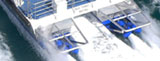
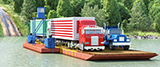
Pipelay and pipe repair is currently being performed by contractors on the lake, using barges with typical lengths of 40 to 50 meters. The barges use anchor-mooring systems to hold them in position and to move forward while laying pipe. The anchors frequently damage other existing pipelines resulting in oil and gas leaks and requiring additional repairs. PDVSA wants to solve these problems by banning` the use of anchors in these operations. This requires dynamic positioning of the pipelay and pipe repair barges.
Dynamic Positioning
Dynamic positioning is a relatively new technology. It was primarily developed for deep water drilling applications, where the use of anchor mooring systems was no longer practical.
The first DP vessel was the Cuss I, which was used in 1961 for core drilling operations off California and Mexico in deep water, up to 3,500 meters. The vessel used four (4) deck mounted azimuthing thrusters mounted over the side at the four corners of the vessel. The thrusters were direct engine driven and were manually controlled. The vessel could stay on station within a radius of about 180 meters. Due to the depth of the water, the great length of the drilling stem had enough flexibility to allow such a large operating envelope.
Simultaneous manual control of the four thrusters was a difficult task, so the idea was developed to use a computer to control the thrusters. This was done for the first time in 1961 on the coring drill vessel Eureka operated by the Shell Oil Company.
Many vessels have since been equipped with DP capability. As computer technology and experience and knowledge about dynamic positioning increased, the systems became more sophisticated and reliable. Today, there are three major suppliers of DP controllers and software. First there is Kongsberg-Simrad, with the combined technology and experience of Robertson, Albatross, Kongsberg and Simrad. Second, there is Nautronix, who acquired the Honeywell technology and experience. Third, there is Alstom who bought Cegelec. In addition to these three majors, there are some small companies that have recently developed their own DP systems. These new systems are relatively simple and lack many of the built-in special software and safety features that come with the time-proven systems of the three established major suppliers. Although the new systems are offered at much lower cost, there are not many of them in use. So far, these newly developed systems have been used in non-critical applications only and there is insufficient operating experience to determine their reliability. They have never been used in pipelay service.
Dynamic positioning is used in quite a few different applications. Some of these are simple and not very critical, like the DP system on a deep water supply boat that just has to stay in the vicinity of an offshore platform while offloading supplies. In such applications, accuracy of 5 meters is perfectly acceptable and heading is unimportant. The vessel will normally turn its bow into the wind. Once the cargo is offloaded, the vessel goes off DP and uses its normal propulsion to sail back to port. If, during offloading, the DP system were to fail, the Captain can take over with manual controls and complete the operation.
Other applications are much more critical. An example is oil drilling in deep water. That requires the vessel to be on DP 24 hours a day for months at a time. In this application, reliability is extremely critical. If the vessel were to drive off location, the drill stem breaks and a blow out may result. The associated costs of such a drive-off are extremely high. Consequently, those systems require a high degree of reliability and redundancy. Accuracy is not that critical, as excursions of up to 10 meters generally do not cause any problem due to the great length of the drill stem in deep water.
Pipelay is one of the most critical applications for dynamic positioning. Not only are environmental forces acting upon the vessel, but also the suspended pipe will create additional forces acting upon the barge. The vessel must maintain position and accurate heading control. If the vessel loses it’s heading, the pipe comes under great bending load, which may result in pipe breakage or failure of pipe handling equipment on deck. This may cause damage and injuries. The need for accuracy becomes increasingly important in shallow water depths where the length of the pipe suspended between the barge and the bottom is short. This short length does not allow much flexing to accommodate for vessel drive-offs or heading changes. Very good slow speed tracking control capability and very accurate control of position and heading is essential in this application.
Today’s dynamic positioning systems use software that includes a mathematical model of the vessel. This is developed for each individual vessel and it contains information about vessel wind drag, vessel current drag, center of gravity, center of rotation, location of thrusters, etc. With the help of this mathematical model, the DP controller issues the proper commands to the thrusters on a continuous basis to maintain desired position, heading and speed of the vessel.
The controller gets frequent updates from position reference sensors (such as DGPS), heading references (gyro compass) and the speed and direction of the wind (anemometer). There are two different ways that prompt the DP controller to take corrective action. The first is position feedback. If the position reference signal indicates that the vessel is off location, the controller takes corrective action by making the thrusters get the vessel back on its required position. The second is wind feedforward. As wind direction and speed change, the controller makes the thrusters correct for this, before the vessel is moved off position.
Thrusters Used for Dynamic Positioning
Most DP applications are for large vessels operating in deep water. Modern drill ships use thrusters in the range of 4,000 to 8,000 HP. They are electric motor driven with variable speed control.
Platform supply boats normally use tunnel thrusters or retractable thrusters for station keeping. They are mounted inside the hull and they may be direct, electric or hydraulic drive.
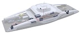
Deep-water pipelay barges typically use retractable thrusters mounted inside the hull. The thrusters are retracted during long tows and when going in and out of port. The barges normally have one or two large engine rooms with diesel generators and electrical control equipment. The thrusters are driven by electric motors with speed control.
On small barges, the hull depth is usually insufficient to use retractable thrusters inside the hull. Consider that a 300 HP retractable thruster already requires a hull depth of not less than 12 ft. For conversion of existing barges, creation of large machinery spaces and installation of diesel generator sets, electrical control equipment and retractable thrusters is not practical. For these applications, deck mounted thrusters are much more suitable and economical.
The typical deck mounted steerable propulsion unit, used on self-propelled barges, uses a diesel engine with clutch driving a cardan shaft connected to a Z-drive style azimuthing thruster. This type of thruster uses a horizontal input shaft with an upper right angle gear assembly driving a vertical drive shaft which, through a lower right angle gear assembly drives the propeller shaft (like the letter Z, hence the name Z-drive). They steer through 360 degrees without stops. They are commonly referred to as rudder propellers. The concept is old and well proven. Such units were used for positioning of the very first DP vessel, the Cuss I. However, these units have certain limitations that make them unsuitable for use in shallow water pipelay operations. An explanation as to why conventional rudder propellers with direct engine drive are not suitable for this application follows below.
Thruster Sizing
Sizing of thrusters is critical. Nobody ever got in trouble because of too much thruster power, but many people got in trouble because of insufficient power.
Thrusters must be sized for the worst environmental conditions that the vessel may operate in. In considering this, note that the weather may change while in the middle of a pipelay job. The barge must be able to complete the job under those conditions.
Thruster sizing is normally done by a computer program and is represented in polar diagrams called ACapability Plots@. They are unique for each vessel and preparation of these plots requires input of physical details of the vessel, such as dimensions, draft, displacement, outboard profile and thruster size and locations.
In simplified form, we can manually estimate the forces acting upon the vessel by wind and current. We take the worst case whereby wind and current are both directed towards the same side of the vessel. The following formula is used:
For wind load, F is the force on the barge from the wind. Cd is the drag coefficient of the upper vessel structure. v is the wind velocity. g is gravity acceleration. A is the projected area of the vessel above the waterline, exposed to the wind. ρ is the density of air.
For current, F is the force on the barge from the current. Cd is the drag coefficient of the submerged portion of the hull. v is the velocity of the current. A is the projected area of the vessel below the waterline exposed to the current and ρ is the density of water.
Suppose that we design for a wind velocity of 45 knots and a current of 1.5 knots. Then, let us assume that the wind force calculation indicates that we need 600 HP of equivalent thrust and the current force calculation indicates that we need 200 HP of equivalent thrust. So the total HP required to counteract wind and current would be 800 HP. Since redundancy (DPS-2) is required, the vessel must still be able to hold position under these conditions upon failure of one thruster. Accordingly, let us assume that we calculate that we need four (4) each 300 HP thrusters to do this (1200 HP total).
Now, let’s assume that we start operating with this barge and the wind is blowing at 14 to 25 knots and there is no current. Since wind velocity is squared in the formula, the total force from the wind would be equivalent to 60 to 180 HP, since ![]() Since we have four thrusters, each thruster needs to develop one fourth of this, i.e., 15 to 40 HP. However, we have four thrusters of 300 HP. So, when wind speed is 14 to 25 knots, the thrusters are running at only 5 to 15 percent of their capability. This is very typical of DP applications. Most of the time, DP thrusters are running at only a small percentage of their rated output.
Since we have four thrusters, each thruster needs to develop one fourth of this, i.e., 15 to 40 HP. However, we have four thrusters of 300 HP. So, when wind speed is 14 to 25 knots, the thrusters are running at only 5 to 15 percent of their capability. This is very typical of DP applications. Most of the time, DP thrusters are running at only a small percentage of their rated output.
Direct Engine Driven Thrusters
With diesel-electric or diesel-hydraulic
driven thrusters, all thrusters work
together as a team, each thruster
contributing in countering wind and
current loads.
With direct engine driven thrusters,
half of the thrusters must counteract
the thrust of the other half, in
addition to countering
wind and current loads.
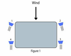
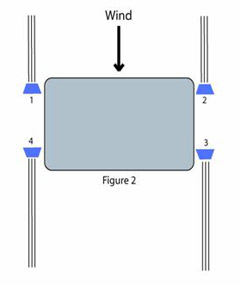
Ideally, all four thrusters are working together to counteract the wind force. But this is a problem when using direct engine driven thrusters. At full engine speed, say 1800 RPM, the thruster puts out maximum thrust. But even at low idle speed, say 600 RPM, the thruster still produces 12 to 13 percent of its maximum thrust. At 14 knots wind, that is far too much, since we only need 5 percent of maximum thrust. Accordingly, we cannot operate with the thrusters shown in the arrangement of Figure 1. We will have to steer two thrusters against the wind and two thrusters in the opposite direction, as shown in Figure 2.
Thrusters 1 and 2 are running at low idle speed (each at 13 percent output) while thrusters 3 and 4 are not only counteracting the wind force, but also counteract the thrust produced by thrusters 1 and 2. As the wind speed changes, thrusters 3 and 4 speed up and down to hold the barge in position, while thrusters 1 and 2 continue to run at idle speed in the opposite direction.
Diesel engines are designed to operate within a certain speed range. For instance, an engine rated at 1800 RPM runs well in the range from 1200 RPM to 1800 RPM. At slower speeds, the engine runs at poor fuel efficiency and it becomes difficult to control the speed of the engine. Also, at slow speed, the engine produces very little torque, usually only slightly more than the torque absorbed by the propeller. There is not much excess torque available for acceleration. This results in slow response when increasing the speed setting. Moreover, the engine has no capability of forcing the propeller speed down. Reducing the speed is done by reducing the fuel rack setting, which makes the engine coast down. Response to DP commands for changing speed is therefore slow and sluggish at these low engine speeds. This results in lack of station keeping accuracy of the barge during changes in wind and current speed and direction.
It really gets bad when one of the thrusters were to fail. Suppose that in Figure 2, thruster #3 suddenly failed. Now, thruster #2 is helping the wind pushing the bow of the barge around. Of course, the DP system will immediately try to steer thruster #2 in the opposite direction, but this takes time (at least 10 to 15 seconds). By that time, the barge completely lost its heading.
Station keeping with direct engine driven thrusters is certainly possible, and we have done it in the past. However, the accuracy of station keeping is not very good and recovery from mishaps is very slow. While that may be acceptable in some applications, it is not acceptable for pipelay operations, especially when working in shallow waters.
Diesel-Electric and Diesel-Hydraulic Driven Thrusters
With diesel hydraulic and diesel electric drives, the engines run continuously at their rated speed, like a generator set. In a diesel electric system, the thruster is driven by an electric motor with a variable speed drive. In a diesel hydraulic system, the thruster is driven by a hydraulic motor operating in a closed loop hydrostatic system. The propeller speed is controlled by the swash plate controller of the pump, which gets its electrical control signal from the DP controller.
The propeller speed is infinitely variable from full forward to full reverse. Full torque is available at any propeller speed, so changes in speed setting are very fast and accurate, even at very low propeller speeds. This makes for a very responsive system whereby all four thrusters are positively contributing to counteracting the forces from wind and current, as shown in Figure 1. Reactions to changes in wind or current speed and direction are very fast, maintaining very steady position and heading of the barge. And if one of the thrusters were to fail, the other thrusters instantly take over, since they are already in the proper steering orientation.
For the above reasons, applications requiring accurate dynamic positioning use diesel electric or diesel hydraulic thruster drives. While diesel electric and diesel hydraulic drives are much more expensive than direct engine drives, the performance and the reliability is much better. More importantly, it provides the level of accuracy necessary for shallow water pipelay operations.
Brown Water Operation
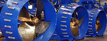
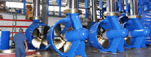
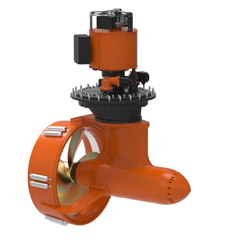
Deep water operation (also referred to as blue water), poses little risk of physical damage to the thrusters. However, in shallow water (also referred to as brown water) there are real dangers of the thrusters hitting large objects on the bottom or other mishaps, such as ropes or tree trunks getting stuck in the propeller. Therefore, thrusters used in brown water must be stronger and better capable of coping with grounding and sudden propeller blockage. Thrustmaster’s podded hydraulic drives are specifically designed for brown water applications.
If the propeller is suddenly blocked on a direct engine driven Z-drive, the engine flywheel inertia will shear a shaft or break gears in the thruster. Repair is complicated and time consuming. Replacement gears and bearings are very expensive and gears have long delivery times.
Propeller blockage on a Thrustmaster podded hydraulic drive is easily absorbed by the pump pressure compensators and hydraulic reliefs. Since the rotating inertia is very small (only the propeller, propeller shaft and rotor of the hydraulic motor) there is usually no damage at all. The hydraulic tilt of the thruster allows easy removal of the object blocking the propeller, and the thruster can be put back into use immediately.
A direct engine driven Z-drive uses right angle gear transmissions and drive shafts in the stem. The whole outdrive is completely filled with lube oil. If the nozzle were to hit a large object on the bottom of the lake, the stem breaks and the lower end of the thruster falls down on the bottom of the lake. All the lube oil is spilled into the water.
Thrustmaster’s hydraulic podded drives use a very strong stem that contains hydraulic hoses only. The drive does not use any right angle gear transmissions or drive shafts. If the nozzle were to hit a large object and the stem were to break, the hydraulic hoses will prevent the lower unit from falling to the bottom. Repair is easy and there is no loss of oil into the water.
Conclusion
Using dynamic positioning for pipelay and pipe repair operations on Lake Maracaibo is certainly feasible and will result in more efficient operations. A high degree of positioning accuracy is required. This requires a top class DP controller system with accurate sensors and very responsive thrusters with full speed range capability in forward and reverse. Thrustmaster of Texas has the experience, the know-how and the right products for this application.
